
n
1. TDC IE communication introduction
TDC system is the newest digital control system of SIMADYN D family and it has the highest quality in the SIMATIC control system family.n
As one part of TIA family it has powerful communication function. The system provides the MPI communication protocol, Profibus communication protocol, Ethernet communication protocol. It is easy to communicate with other simatic product, for example S7-300, S7-400, HMI and drives product.n
For Ethernet communication, the hardware platform is CP51M1 which supply a standard RJ45 Ethernet interface; the old interface CP5100 is discontinued as per Aug. 1 2005.n
For communication task, system can exchange process data with other TDC system or PLC S7 system through CP51M1 module.n
For communication protocol, TDC system supplies TCP/IP protocol and/or UDP protocol.n
For transfer modes, refresh mode, handshake mode, multiple mode and select mode are available for selection.n
For net speed it can work with 10Mbit and 100Mbit network, the module can automatically sense the net speed.n
2. TDC configuration steps
2.1 Hardware configuration in SIMATIC Managern
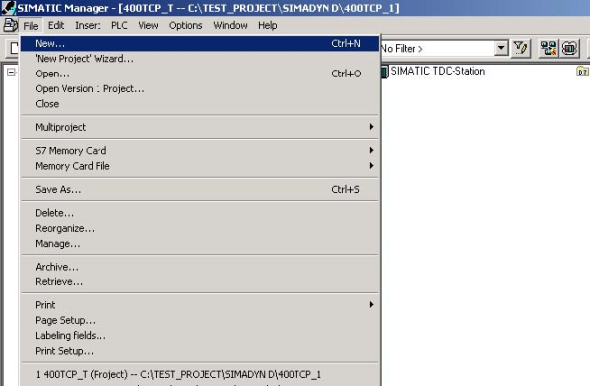
2.1.1 Create a new S7 projectn

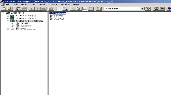
2.1.2 Insert a TDC statio

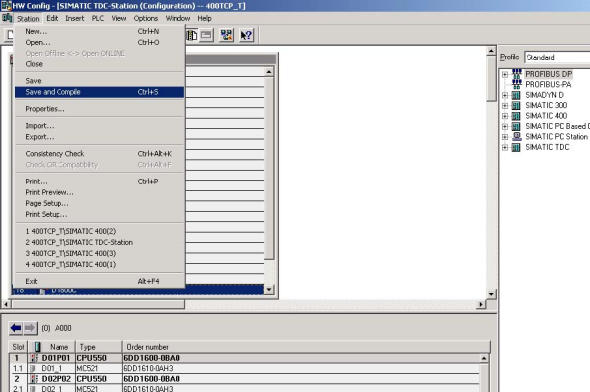
2.1.3 Select hardware configuration in SIMATIC Manager, double click to open itn
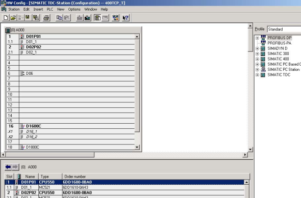
2.1.4 Insert the subrack, CPU, communication board CP51M1 and other module from the hardware catalog
Keep the same type with which is used in the sub rack.n
2.1.5 Define the CPU module and communication module propertiesn
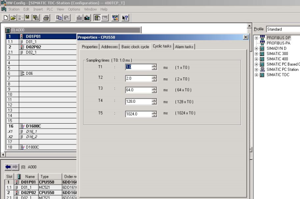
For CP51M1, we need to define the module name firstlyn

For Ethernet property we need to define the IP address and subnet maskn

2.1.6 Save and compiled the hardware configuratio
2.2 CFC programmingn
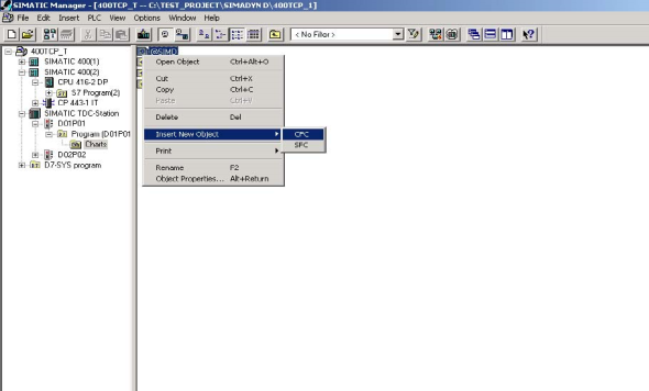
2.2.1 Insert a CFC program in SIMATIC Manager, double click it to open itn
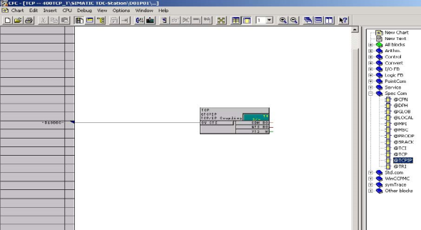
2.2.2 Insert the TCPIP communication block into the chart, define the coection address which is set in the hardware configuration and select the proper cycle timen
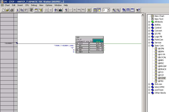
2.2.3 Insert the send function block CTV_P, define the coection:n
| CTS | P51M1 hardware address which is set in hardware configuration | |||||||
| AT | chael name.protocol type–CP51M1 port number.partner IP address–partner port number, for example: 'TRAN.T-02004.192168000003-02002’ |
|||||||
| MOD | ormally we select handshake mode | |||||||
| EN | set to 1 to enable the FB | |||||||
| NBY | define the telegram length in bytes | |||||||
2.2.4 Insert the DWR_D block to write the communication content to the communication buffern
Here we can define the offset in the communication buffer by set coector1/2. The final result is the sum of offset1 and offset2.n
For coector SWP we set it to 1 if it communicates with a PLC.n
The data we try to send is set in coector X, here is 44 as an example.n

For receive part, we can do it in the same way.n
For coector AR of CRV_P, we do not need to define the partner IP address–partner port number.n
2.2.5 Compiled the program and download it to the memory card and restart the systemn
3. S7-400 configuration steps
3.1 S7 hardware configuratio
First insert the S7-400 station, and then open the hardware configuration to insert the modules which are available on the sub rack.n
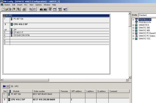
For CP443-1 module we need to define the IP address and subnet mask.
The IP address will be used in the CFC program.n
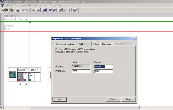
3.2 network configuration in the Netpro software
Open Netpro under hardware configuration menun

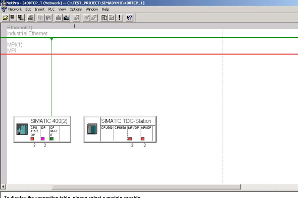
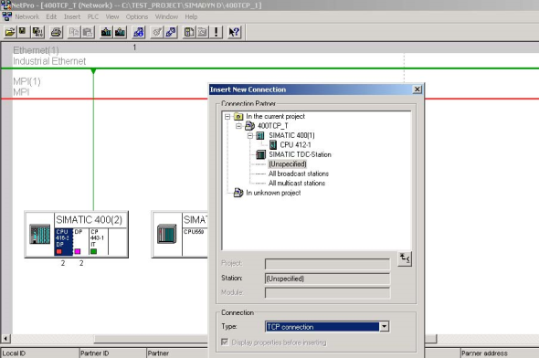
Select the CPU in the SIMATIC station and insert a new coection,
Select unspecified station and
TCP coection, press apply button.n
Select the ID number, record the address LADDR.
Both of them will be used in the S7 program.n
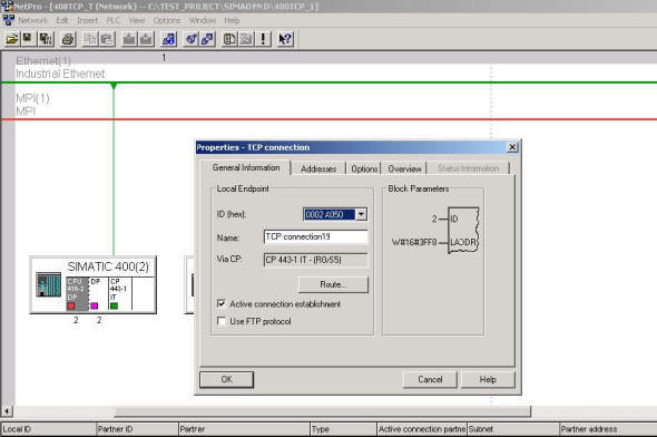
Under address menu we need to set the local port number, partner address and port number, press OK button to confirm the setting.n
For other coection you need, you can do it in the same way.n
Then we need to save and compile the configuration.n
We need to download not only the hardware configuration, but also the Netpro configuration to the CPU.n

3.3 Programming in the S7 CPUn

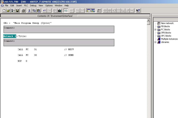
For the industrial Ethernet communication we use the FC5 AG_SEND, FC6 AG_RECV block.n
These blocks transfer and receive the data on the configured TCP coection to and from the Ethernet CP.n
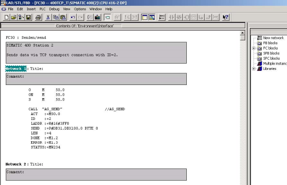
Here we made two FC separately for send and receive function, one is FC 30 for FC5, and another is FC31 for FC6.n
For FC5, we need to define:n
| ACT: | set it to one to trigger FC | ||||||
| ID: | coection ID number which is set in Netpro | ||||||
| LADDR: | CP module start address which is set in hardware configuration, also | ||||||
| available in Netpro. The address is in HEX mode, for example 3FF8H | |||||||
| SEND: | set the transfer data address and buffer length | ||||||
| keep the format for example P#DB31.DBX100.0 BYTE 8 | |||||||
| LEN: | umbers of bytes to be send from the transport data area with this job | ||||||
| DONE: | bit signal for executed status | ||||||
For error evaluate we can check the coector Error and Status. For the status code we can get detail information in the FC5 description documentation.
For FC6, we can do it in the same way.
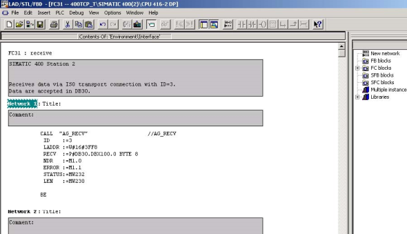
Because we use DB30 and DB31 in the program FC30 and FC 31, we must insert these two data block and download it to the CPU.
4. Physical coection
TDC side: CP51M1 supply RJ45 interface
S7 side: CP443-1 supply RJ45 interface
Between the double sides we need a Switch to coect.
关键词
工业以太网,硬件组态,CFC,连接,PLC 编程
原创文章,作者:ximenziask,如若转载,请注明出处:https://www.zhaoplc.com/plc327185.html
 微信扫一扫
微信扫一扫  支付宝扫一扫